Specify the generator around the prime mover and the electrical load.
A permanent magnet generator inquiry begins with the full operating range: shaft speed, mechanical input, required electrical output and the converter or load it must serve. Use the PMG route to organize those inputs before configuration review.
For energy-system integrators, equipment OEMs and technical buyers.
The generator sits between a variable mechanical source and an electrical requirement.
Wind, hydro and industrial prime movers can each present a different speed and torque profile. The electrical side may require a rectifier, converter, DC link, storage interface or controlled AC output.
Speed range, torque, starting behavior and overspeed.
Electromagnetic, thermal and mechanical design.
Voltage, current, frequency and protection boundaries.
This is a system diagram, not a wiring design. The generator and power electronics must be checked across the complete operating envelope.
One generator conversation, defined by actual duty.
“PMG” and “PMSG” describe permanent magnet generation; they are not presented here as two confirmed ENNENG model families. The product page introduces the available generator route, while the PMSG guide explains the synchronous operating principle.
For a proposal, define rated and minimum speed, the mechanical input available at each point, target voltage and power, phase arrangement, cooling, mounting and the connected converter or load.
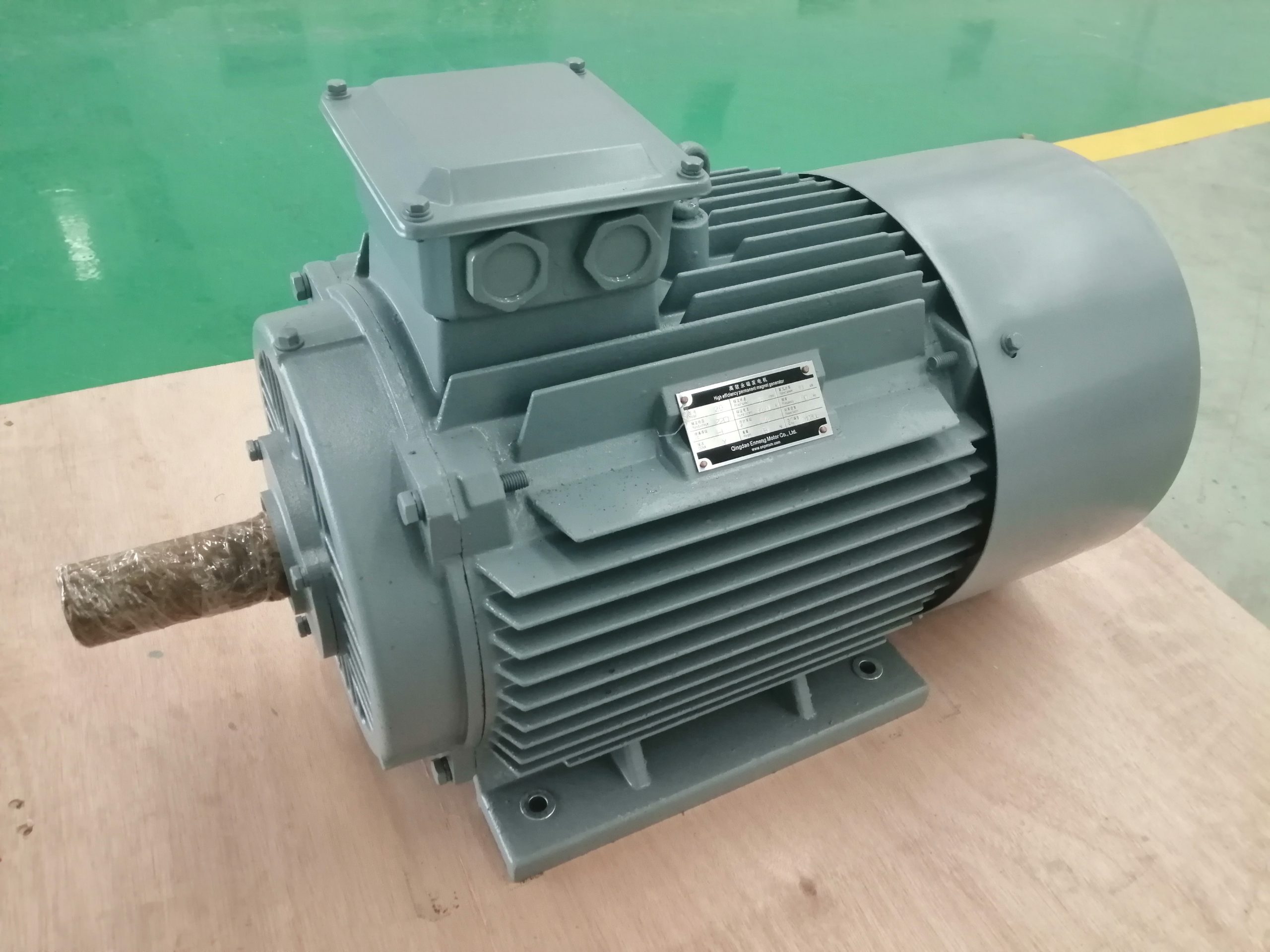
Separate the application from the product evidence.
The following images illustrate possible generation settings. They do not represent verified ENNENG installations or performance results.

Variable input speed
Define cut-in, normal operation and overspeed. The torque available from the turbine and the converter operating window both affect generator selection.
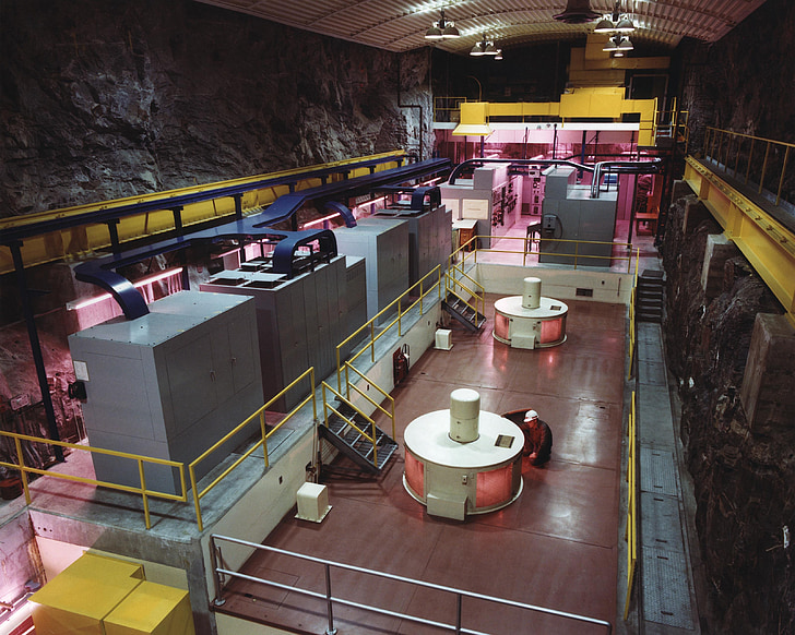
Known electrical demand
State the load type, voltage tolerance, control arrangement and duty. Mechanical drive and electrical output should be evaluated together.
Define the input and output at the same operating points.
A single rated power value hides the conditions needed to review winding, current, cooling, converter matching and mechanical strength.
Minimum, rated and maximum RPM; continuous and transient shaft torque; starting and overspeed events; prime mover and shaft drawing.
Required phase arrangement, voltage range, power or current at each speed, load type, rectifier or converter, DC-link or grid requirements.
Duty hours, ambient and cooling, enclosure, vibration, mounting, service access and the protection responsibilities of each system component.
For variable-speed equipment, identify whether a voltage target applies at open circuit or under load. Load rejection and converter shutdown also need a defined response.
Open generator selection guideClarify the terms and boundaries.
Is PMG the same as PMSG?
PMG is a broad product term. PMSG specifies a permanent magnet synchronous generator. A project still needs a defined machine configuration, electrical output and operating envelope; the names alone do not identify separate product series.
Can rated power and RPM determine generator voltage?
No. Winding design, load, power electronics and the speed range are also needed. State the required terminal or DC-link behavior and whether the value is open-circuit or under load.
Why discuss overspeed and load rejection?
Generator voltage and mechanical stress can change when speed rises or an electrical load is removed. The prime mover, converter and protection scheme must be reviewed together.
Separate system principles from product claims.
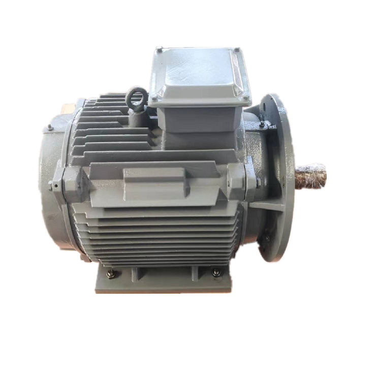
The ENNENG images document source material available to this project, while the wind and plant scenes provide application context only. They are not presented as verified customer installations. The research below explains general permanent magnet generator and wind-system principles; it cannot establish the performance of a specific ENNENG machine. A model proposal should attach a generator data sheet, speed-dependent electrical values, mechanical and cooling limits, converter compatibility, protection assumptions and the planned acceptance points. Confirm every figure against the actual project configuration.
Tell us what turns the shaft and what the electrical system needs.
Send speed, torque or power, voltage, load and mounting constraints. Mark estimates clearly so the next technical discussion can focus on the missing data.