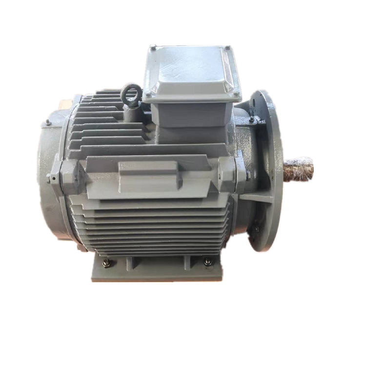
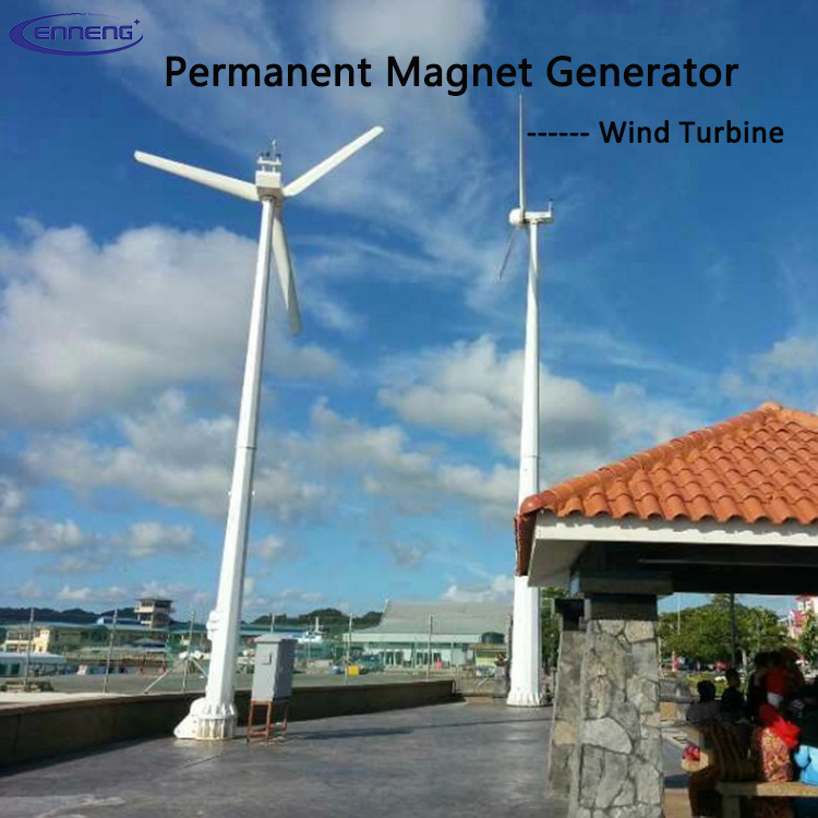
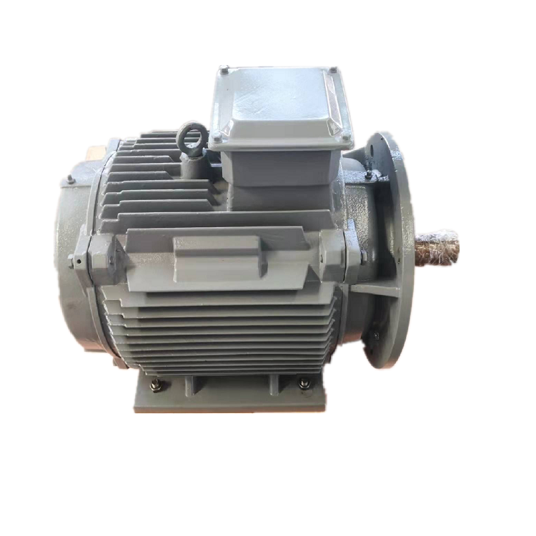
How a PMSG generates electrical power
A permanent magnet synchronous generator uses rotor magnets to establish magnetic flux. Rotation changes the flux linkage of the stator windings and induces an alternating voltage. Electrical frequency is related to mechanical speed and pole count. Terminal behavior then depends on winding design, load, internal impedance, temperature and the connected power electronics. The principle is simple, while the usable system envelope requires electromagnetic, thermal and mechanical design.
Permanent magnets remove the need for a separate rotor field winding and its excitation system, but magnet material and rotor construction introduce their own design constraints. Demagnetization margin, short-circuit behavior, overspeed retention and thermal conditions need review. Do not infer these limits from a generic PMG definition. They belong in the project-specific technical data and verification plan.
Speed, voltage and frequency are linked
For a synchronous machine, electrical frequency follows rotational speed and pole count. If a project requires fixed grid frequency while the prime mover operates over a variable speed range, power electronics usually decouple generator frequency from grid frequency. NREL describes full-converter wind turbine models in which the converter handles the generator output and controls the grid interface. The converter architecture is therefore a core selection input, not an accessory chosen at the end.
State whether the desired output is variable-frequency AC, regulated AC, rectified DC or a DC link feeding an inverter. Include voltage range, current, power factor or DC-load behavior and fault expectations. For battery charging or isolated loads, describe the downstream regulation and protection. This prevents a winding optimized for one interface from being proposed for a different electrical system.
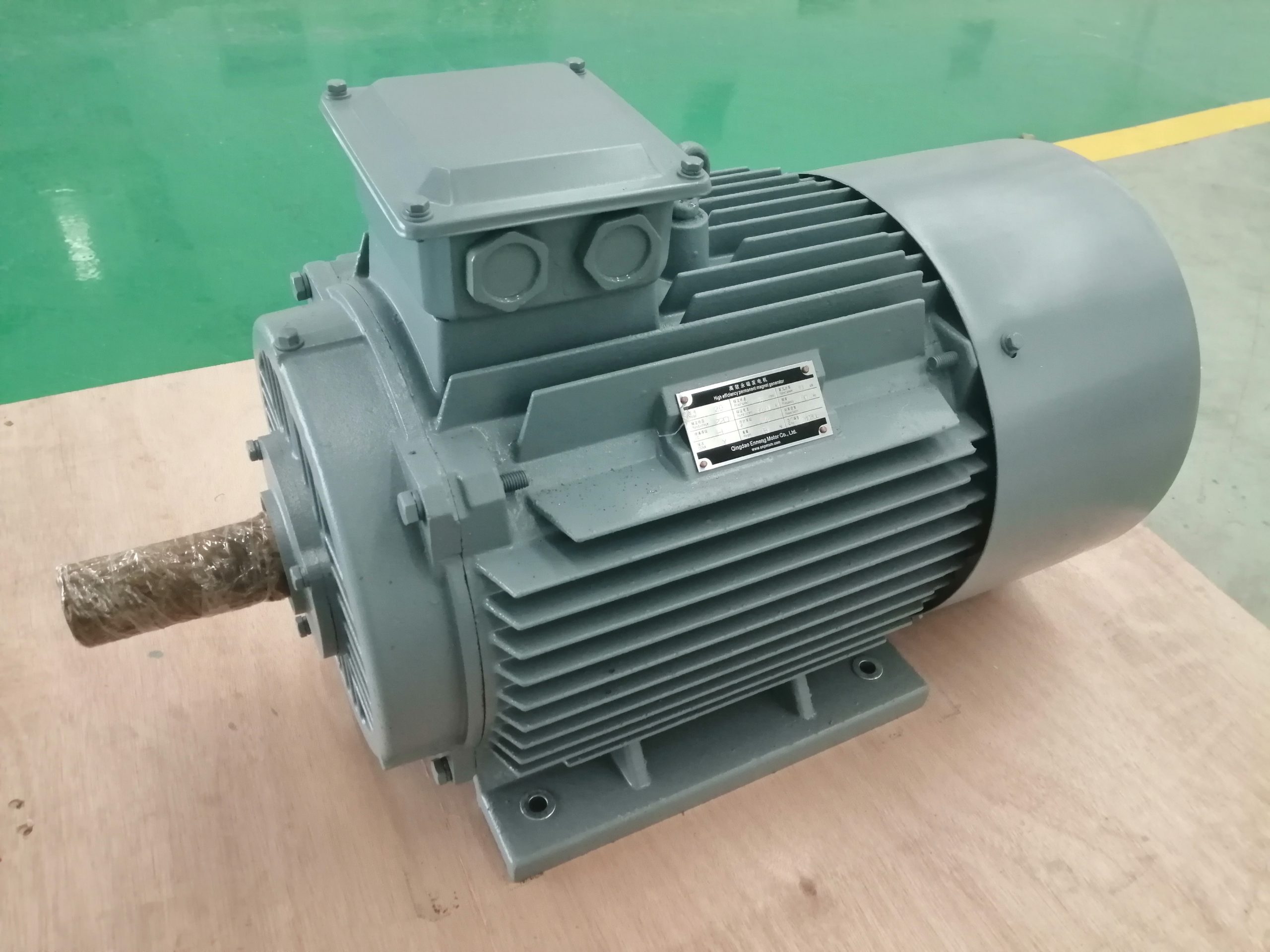
Cogging, starting and low-speed behavior
Permanent magnet machines can exhibit cogging torque due to the interaction between rotor magnets and stator slotting. NREL research on advanced PM generator topologies identifies cogging torque as a design concern because it can affect self-start behavior, noise and performance in small wind systems. The importance of cogging depends on the prime mover, inertia, starting torque and control architecture.
If self-starting at low input torque matters, provide the prime-mover torque-speed curve and minimum useful speed. If the generator is driven by an engine or controlled turbine with ample starting torque, priorities may differ. Describe permissible torque ripple, noise and vibration so these factors can be evaluated against the actual application rather than treated as universal pass-fail labels.
Converter and protection coordination
The generator and converter must agree on voltage range, current, switching, insulation stress, short-circuit response, DC-link control and braking or dump-load strategy. Define what happens during load rejection, grid faults, overspeed or converter shutdown. The system needs a safe path for mechanical input energy when electrical power cannot be delivered normally.
Protection may include temperature, overspeed, overcurrent, overvoltage, vibration and cooling supervision. The exact list depends on the system hazard analysis. Clarify whether protection resides in the generator sensors, converter, turbine controller or plant control system. Assigning these functions early avoids gaps and duplicate assumptions during commissioning.