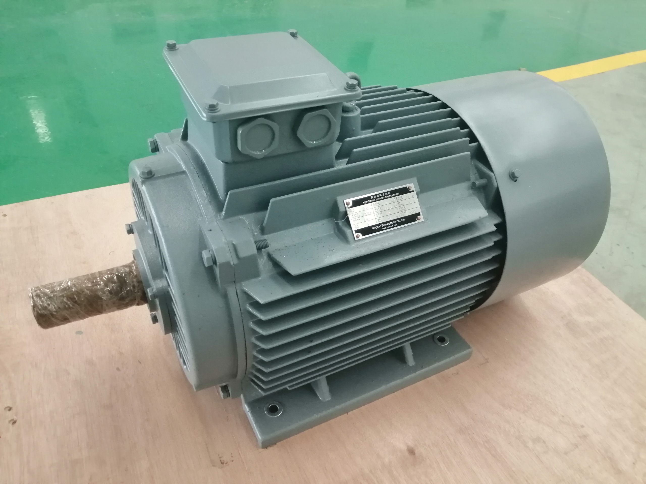
A permanent magnet alternator uses magnets on its rotor to provide the magnetic field; a wound-field alternator creates that field with current in a rotor winding. Both can generate AC power. The meaningful choice is not the label on a catalog page but the complete duty: speed range, voltage regulation, prime mover, converter, protection, maintenance access and cost. A permanent magnet machine avoids rotor excitation power, yet it cannot adjust magnet strength by commanding field current. That tradeoff changes the electrical architecture.
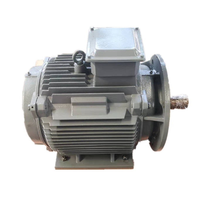
ENNENG's permanent magnet generator archive describes configurable speed, voltage, cooling and installation arrangements, while another archived article discusses permanent magnet and conventional alternator terms. These first-party records support the product category and topics. They do not prove that an ENNENG unit is more efficient, more reliable or less expensive in every application. This guide uses independent technical sources for the machine principles and asks what evidence a buyer should request.
First, clarify what "alternator" means in the RFQ
"Alternator" generally describes an AC generator, not one specific rotor technology. A permanent magnet alternator is therefore a type of alternator. A wound-field synchronous machine is another. Some buyers use "traditional alternator" to mean an engine genset with an automatic voltage regulator and a field winding; others mean any non-permanent-magnet generator. Clarify the exact machine before comparing specifications.
The U.S. National Renewable Energy Laboratory explains that synchronous generators can use a wound rotor or a permanent magnet rotor. Its variable-speed wind technology report also discusses the rotor-field options. Those are architecture differences, not an unconditional maintenance or lifetime result. Bearings, cooling equipment, power electronics and protection can dominate service in either system.
Ask for a one-line diagram. It should show prime mover, shaft or gearbox, generator, rectifier or inverter if used, excitation or voltage-regulation equipment, switchgear, load and grid interface. Without that diagram, two bids may use the same word "alternator" while supplying very different systems.
Compare excitation and voltage control honestly
A wound-field synchronous generator energizes its rotor field electrically. Changing field current gives a control variable that can help regulate the terminal voltage, subject to machine and regulator limits. A permanent magnet rotor supplies a field without that excitation current, so rotor excitation loss is absent. But its magnetic field is not adjusted by a field-current command. Output voltage still depends on speed, winding design, current and load, and regulation may move into power electronics or another system component.
This is why "no excitation" should never be translated into "no controls." The National Renewable Energy Laboratory's variable-speed wind technology report describes both rotor-field approaches and their control implications. A project with a variable-speed prime mover may use a rectifier and inverter to provide a regulated output. A fixed-speed genset may use a different arrangement. The converter or voltage regulator has its own losses, cooling, fault behavior and maintenance needs. Compare measured or calculated performance at the same electrical delivery point.
For an islanded load, identify the largest motor start, step load, permissible voltage and frequency excursion, and recovery requirement. For a grid-connected unit, define interconnection and protection needs. A generator-only voltage figure cannot answer either question. The three-phase generator and converter guide expands the interface checklist.
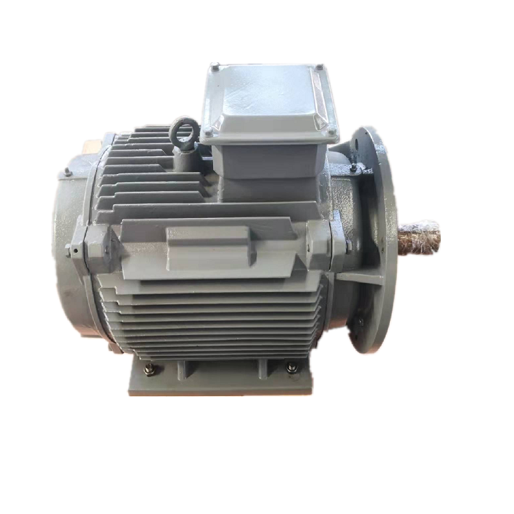
Speed range may determine the rest of the architecture
For a synchronous generator, electrical frequency is related to rotational speed and pole count. A fixed-frequency AC supply therefore requires speed control or an electrical conversion stage if shaft speed varies. Consider a wind turbine, variable-speed hydro turbine or engine operated away from one set point. In each case, the speed profile must be supplied before a winding and converter can be selected. The prime mover's speed and torque envelope is as important as its nominal power.
Low-speed direct coupling can remove a gearbox, but it raises torque for a given power and can make the generator mechanically larger. A high-speed machine behind a gearbox changes the balance of generator size, gear losses and service tasks. The U.S. Department of Energy's wind drivetrain overview illustrates this system tradeoff for turbine architectures. It does not establish that direct drive is always lower cost or more reliable.
Get speed, continuous torque, peak torque, overspeed, inertia and starts or load changes into the RFQ. Ask whether the proposed generator is direct-coupled or geared, and whether the support bearings carry turbine or engine loads. The low-rpm generator selection guide covers the low-speed mechanical questions in more depth.
Examine losses at the same boundary
It is technically sound to say that a permanent magnet rotor does not need electrical excitation power. It is not sound to promise a fixed fuel-saving percentage or project-wide efficiency gain from that fact alone. The final balance includes stator copper and iron losses, mechanical losses, cooling auxiliaries, any gearbox, and rectifier or inverter losses. Wound-field excitation losses matter, but they are one line in a larger ledger.
Compare efficiency maps or test points at the actual operating hours, not one best-case point. In a genset, compare fuel input and delivered electrical energy over a specified load profile only when the engine, controls and measurement conditions are comparable. In a wind or hydro project, compare output against the same wind or water input assumptions. If a supplier gives only generator efficiency, ask for the test method and exact measurement terminals.
The archived ENNENG pages mention broad efficiency and service benefits. This draft does not repeat those claims as project facts because the supporting test boundary and current model-specific evidence were not supplied. A useful offer should identify losses, temperature rise and the operating points used for every number it presents.
Map maintenance and fault behavior, not just parts count
Removing a rotor winding and its excitation circuit may simplify one part of a system. It does not make the generator maintenance-free. Bearings, seals, cooling passages, connections, insulation, sensors and converters still need inspection and sometimes replacement. Wound-field systems have their own excitation equipment, but their field controllability may suit particular operating and grid-support requirements. Maintenance planning should list all installed components and service intervals from the actual supplier documentation.
Fault response deserves its own review. A permanent magnet rotor continues to establish flux when it turns, even if a converter trips. The system must specify isolation, overspeed control, braking or shutdown behavior, and safe work procedures. A wound-field machine can change excitation, but protection still must coordinate with the prime mover, switchgear and load. Do not infer fault capability from "brushless" or "permanent magnet" in a brochure.
If the site is remote, ask how spare parts, lifting access, cooling equipment and converter service will be handled. If a replacement machine must fit an existing base, capture shaft height, flange, coupling, airflow and cable entries before comparing purchase price. These details often decide whether a technically attractive option is installable within the shutdown window.
Use a comparison table for the actual project
Put both offers on one page with the same fields: mechanical input and speed range; continuous and transient electrical output; voltage and frequency regulation method; converter and excitation equipment; loss or efficiency basis; cooling and enclosure; footprint and lifting needs; bearing and coupling boundary; protection; maintenance plan; and accepted test method. Mark a field "unknown" when evidence is missing. A blank in one proposal should not be quietly filled with an assumption from the other.
For a variable-speed renewable system, request a plot or table of shaft speed, available torque, generator voltage, current and delivered output at several duty points. For a genset, define load steps, motor starts and permitted voltage and frequency response. In each case, ask which party supplies the controls and who is responsible for integration testing. A generator alone cannot guarantee a grid-compliant or stable plant output.
An independent NREL direct-drive generator comparison discusses wound-field and permanent-magnet options with attention to size, material and architecture. Its particular study assumptions should not be copied as today's price or ENNENG performance. Its lasting lesson is methodological: compare configurations at a declared duty and include the supporting system.
Questions to resolve before requesting a price
Does a permanent magnet alternator make constant voltage without a regulator? Not by itself across arbitrary speed and load. Its rotor field is present without excitation current, but the terminal behavior and output regulation depend on the machine design and connected electrical system. Ask for the proposed control architecture and performance evidence.
Is a wound-field alternator always the less efficient choice? No. Rotor excitation introduces a loss that a permanent magnet rotor avoids, but whole-system efficiency depends on operating duty, converter or regulator losses, cooling and drivetrain architecture. Require like-for-like measurements or transparent calculations.
Can either machine replace an existing alternator by matching kilowatts? No. Verify shaft and mounting geometry, speed, voltage, frequency, starting and fault behavior, cooling, control interfaces and acceptance criteria. The comparison should identify every changed component, not just the replacement generator.
Technical references
Machine principles and system comparisons were checked against NREL's variable-speed technology report, its WindPACT direct-drive comparison, and the U.S. Department of Energy drivetrain overview. ENNENG's archived pages establish its product discussion only; current project suitability and performance require model-specific technical review.
Bring the operating data into one discussion.
Send the known duty points, electrical interface and mechanical drawings. Unknowns can be marked for follow-up.