Specify mechanical input and electrical output together
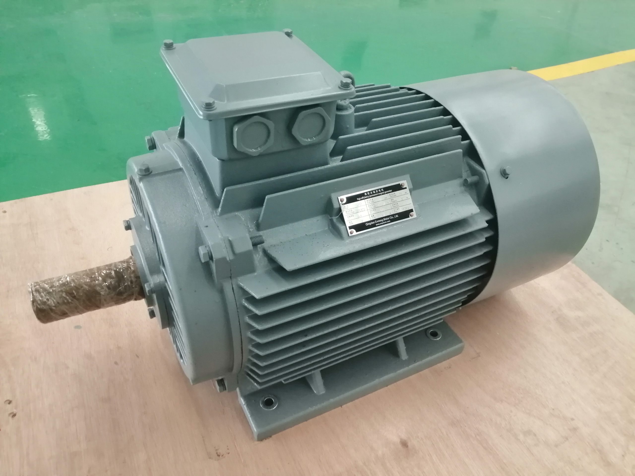
A permanent magnet generator inquiry needs both sides of the energy conversion boundary. On the mechanical side, define shaft speed range, continuous and transient torque, direction, overspeed, inertia and the prime mover. On the electrical side, define rated power, voltage, phase arrangement, frequency requirement, load type, rectification, converter and grid or storage interface. A power value without speed does not establish torque, and a voltage value without speed and winding context does not establish a generator design.
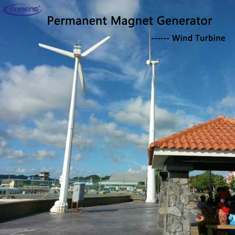
Describe the complete operating envelope rather than one rated point. Wind, hydro and engine-driven systems may spend substantial time away from nominal speed. The electrical interface may regulate voltage or DC-link conditions while mechanical input varies. These control responsibilities should be identified early so the generator, converter and supervisory control are designed as a coordinated system.
Thermal design follows the duty profile
Copper, core, magnet, bearing and power-electronic temperatures influence generator capability and life. Cooling may rely on natural air, forced air, liquid or another project-specific arrangement. The correct choice depends on loss distribution, enclosure, ambient conditions, altitude, contamination and available auxiliary power. Intermittent peaks and sustained part-load operation should be included in the thermal cycle.
Share ambient temperature range, humidity, dust, salt exposure and whether the generator operates indoors, outdoors or offshore. State cooling-fluid conditions when liquid cooling is considered. Temperature sensors and protection logic should be planned with the machine and converter. A rated output should always be read with its cooling and environmental conditions.
Converter and protection coordination
The generator and converter must agree on voltage range, current, switching, insulation stress, short-circuit response, DC-link control and braking or dump-load strategy. Define what happens during load rejection, grid faults, overspeed or converter shutdown. The system needs a safe path for mechanical input energy when electrical power cannot be delivered normally.
Protection may include temperature, overspeed, overcurrent, overvoltage, vibration and cooling supervision. The exact list depends on the system hazard analysis. Clarify whether protection resides in the generator sensors, converter, turbine controller or plant control system. Assigning these functions early avoids gaps and duplicate assumptions during commissioning.
PMG request-for-quotation package
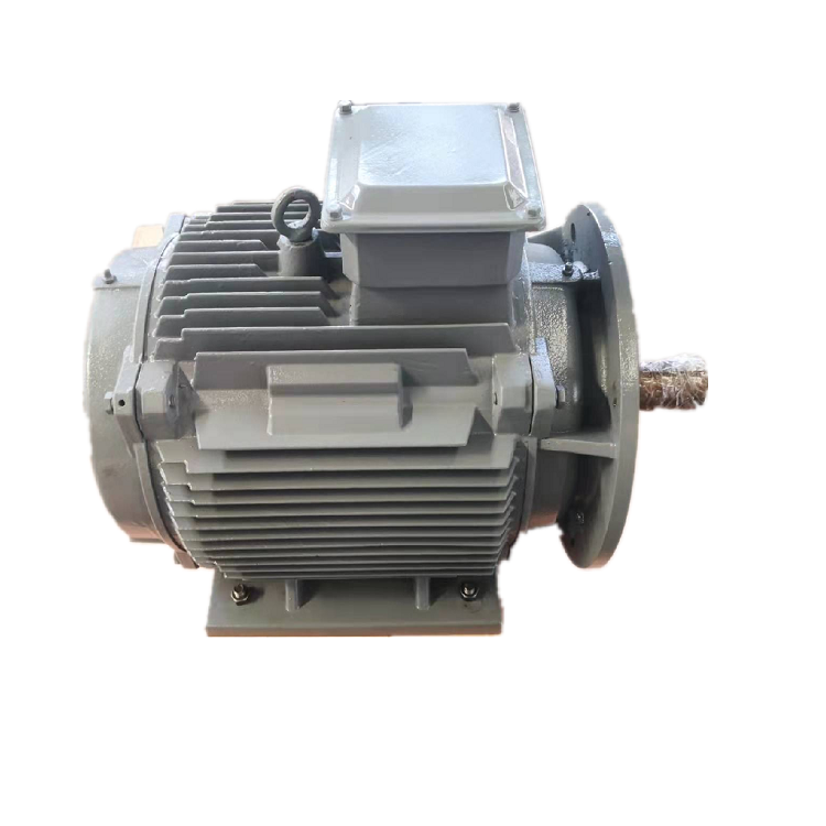
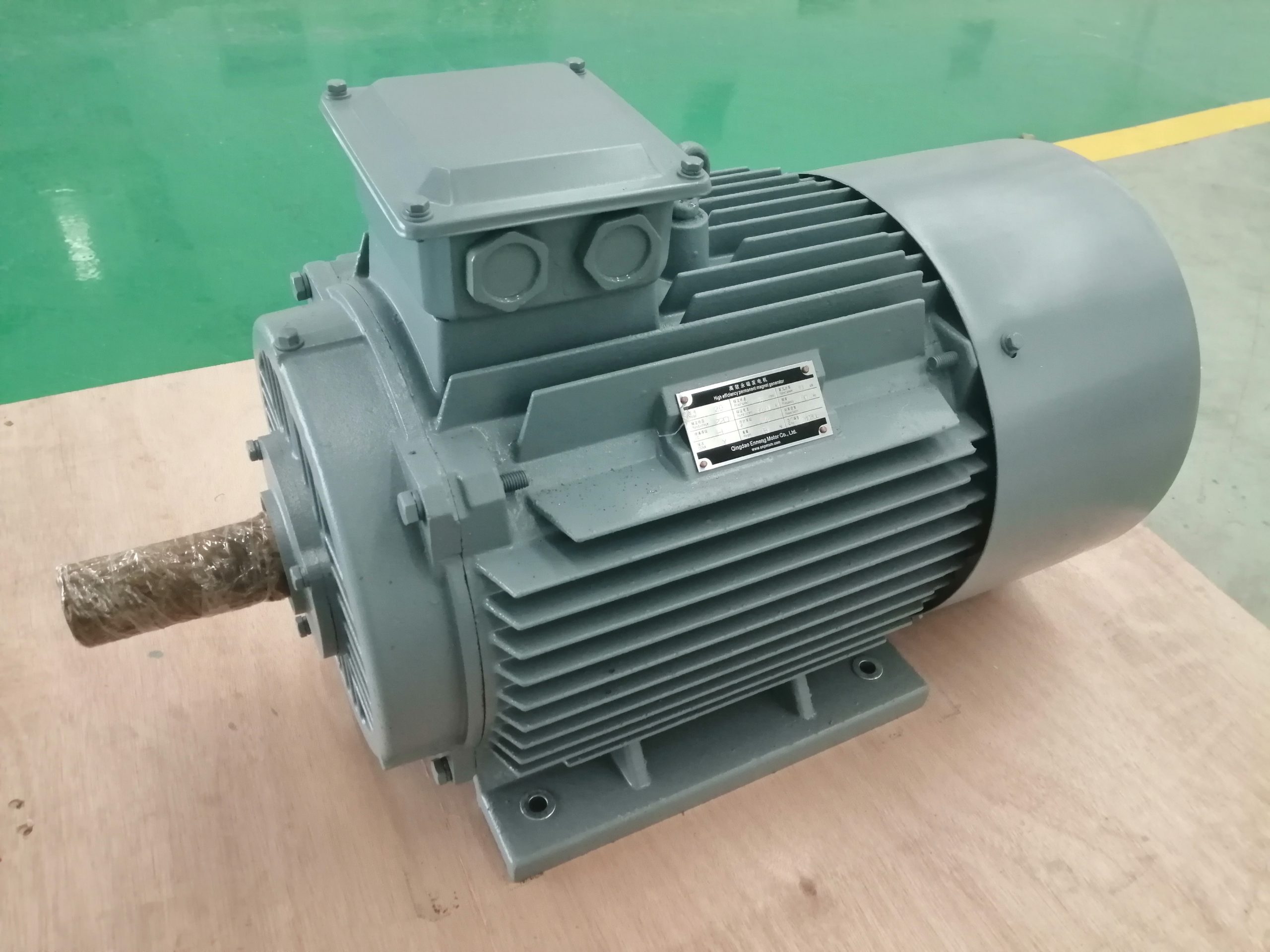
Provide rated and maximum power, nominal and full speed range, continuous and transient torque, desired voltage and phase arrangement, frequency or DC-link requirement, converter details, load type, duty cycle, cooling, environment, overspeed, mounting, shaft and coupling information, allowable envelope and required sensors. Add the prime-mover curve where available.
Mark which values are fixed and which can be optimized. If the project is at concept stage, state the uncertainty range rather than inventing a precise point. ENNENG can then identify feasible directions and the calculations or tests needed next. This creates a technical record that can support design review, quotation and later acceptance planning.